Change in TERRAIN direction.

a "Flower Power" community that may be interested in ANY part of aircraft sim creation ..... from creating models all the way to creating code
sydbod
Flight Sergeant
Flight Sergeant
Posts: 1678
Joined: Sat Aug 13, 2005 12:39 pm
Location: Sydney,NSW,Australia

Change in TERRAIN direction.

Post by sydbod »

Hi All,

I have come across a sticky problem that may cause me to change direction a little bit.

It appears that most video cards and virtually most every game library use single precision floating point numbers for defining in 3D space the node positions for models, as well as the camera position.

The problem that I did not fully appreciate early enough is the following.

A floating point number looses accuracy in the decimal point part of its make up as it increases in size. IE: it is basically an approximation rather than an accurate number.

If I have an aircraft that is a long way away from the 0,0,0 origin point then small changes at that long distance are not accurately recorded in the floating point number.

Here is the problem.

I created a sphere that is at its closest point 0.5 Meters away from the pilot view point camera.

While ever the camera is close to 0,0,0 world coordinates then the floating point number is accurate enough to display that sphere as it should be.

If a person is flying lets say 100KM away from the games 0,0,0 world coordinates center point, then the numbers that the game works with are around 100000.xxx in value.
With such large numbers, the .xxx part is no longer recorded accurate enough.

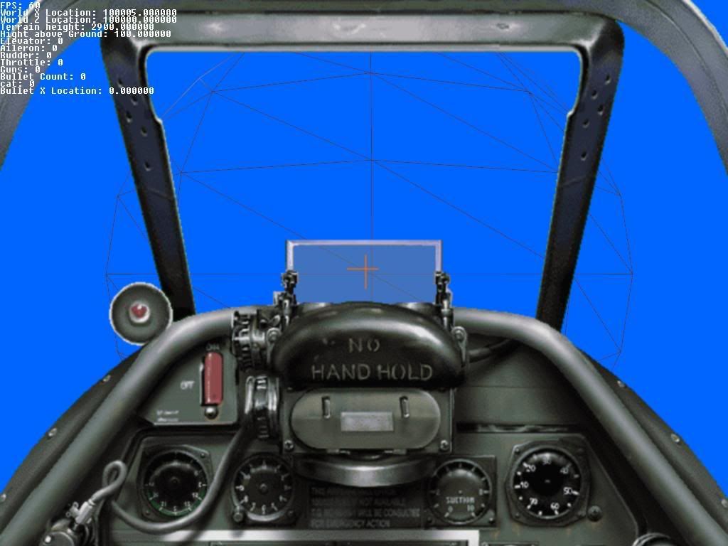
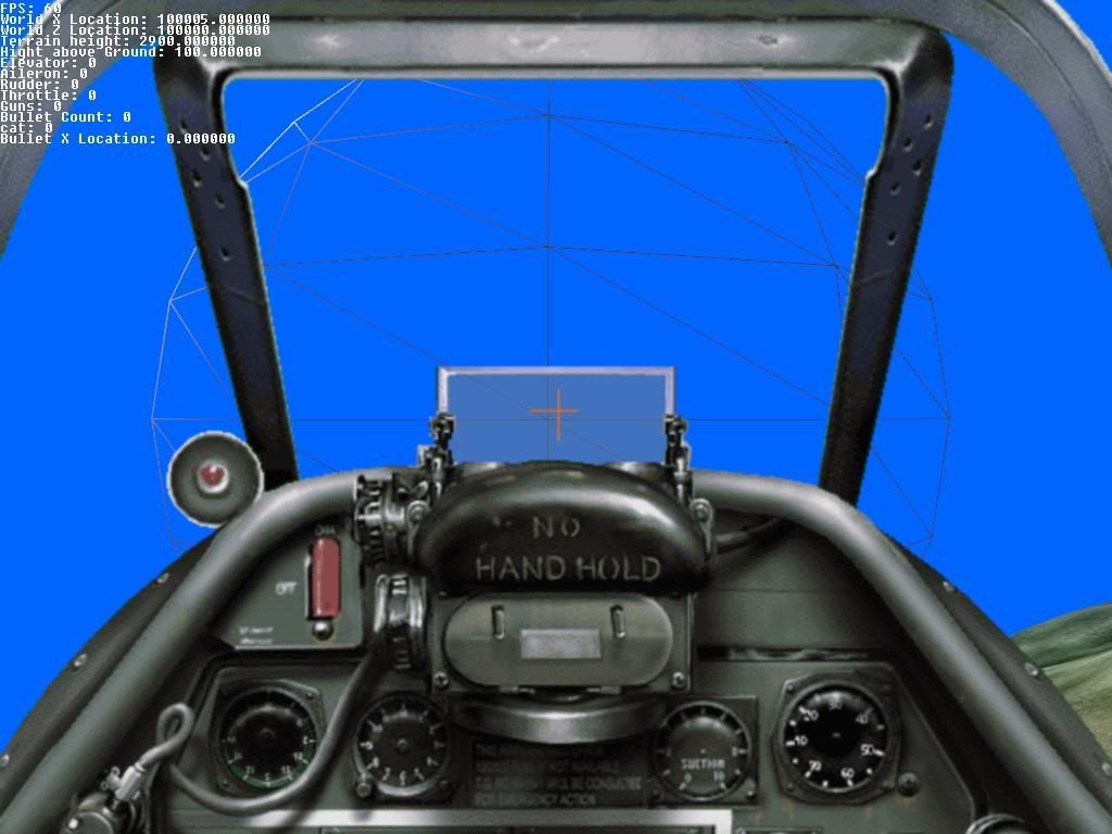
Here are 2 pictures of an aircraft at around 100KM from the world 0,0,0 center point. The aircraft is moved a little between pictures to force the floating point numbers to change a little.
Image

Image

You can see how the center line of the sphere is moved from one side of the target crosshairs, to the other side.

At long distance from the game origin 0,0,0 as the aircraft is moving, the sphere is madly jittering around the place.

The significance of all this is that I want to create 3D cockpits for the game.
These 3D cockpits jitter madly around the place in the same way.

It appears that I will have to re-normalise the camera location to 0,0,0 every frame before adding the 3D cockpit model, and basically fly everything in the game around a stationary camera, rather than fly the player around in a stationary world.

This will require me to change all the data structures and significant parts of the code.
The associate problem is that I have no way of moving the 3D terrain within this game library. I will have to build up my own terrain with discreet meshes and texture it. This will allow me to move my world terrain as I will now require with the new approach. This is another significant increase in code.

Oh well .... we see how things pan out.

Regards Syddy :)
Syddy........Just another breed of COOL CAT
sydbod
Flight Sergeant
Flight Sergeant
Posts: 1678
Joined: Sat Aug 13, 2005 12:39 pm
Location: Sydney,NSW,Australia

Post by sydbod »

Just a small update about the terrain.

While I was creating parts of the new terrain code, it looks like we came across a nasty fault within the game library when using its inbuilt terrain functions.

It appears that when one creates a terrain using the inbuilt functions, then these functions actually chop off some of the terrain from one of the sides.

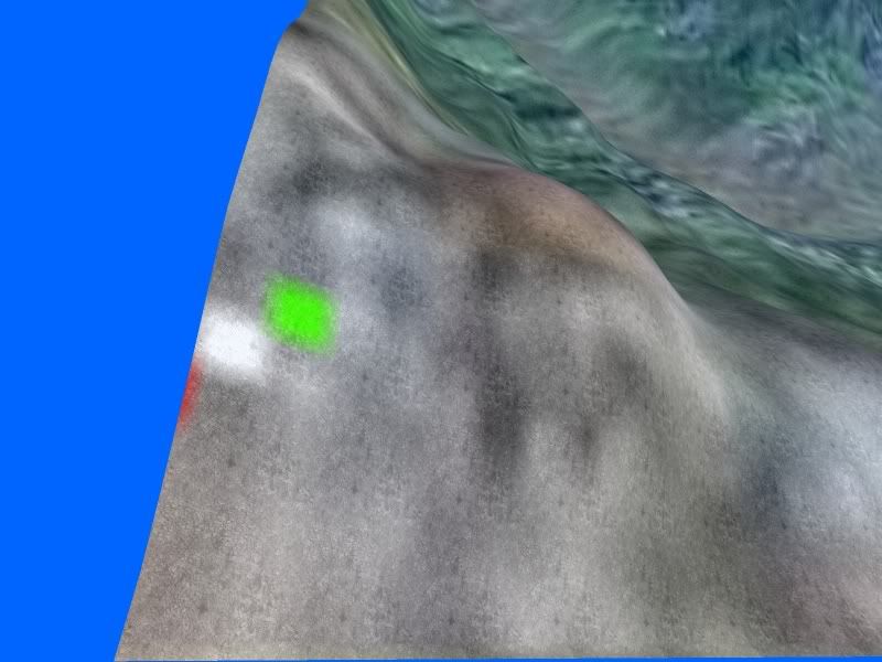
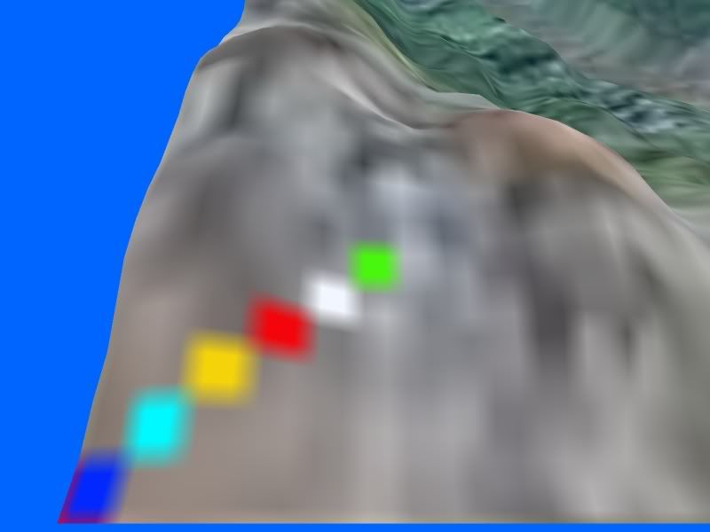
Here are 2 pictures that show the effect:

This is a terrain edge made by the default game library functions ... look at the colored dots on the edge ..... some of the colored dots are missing .
Image


Now the same terrain with some of the newly created terrain code (I still have to implement the high detail overlay part of this code).
Note the color dots ...... they are all there as they should be (as they were on the terrain texture).
Image

It looks like I will give away the idea of ever using this game libraries inbuilt terrain functions, and just create my own versions.

I have decided to make an executive decision of breaking up the terrain into 3 parts. (I tried to have a democratic vote, but even with a membership of only one at the moment I still could not get a majority decision..... , democracy does not work).

Part 1) a high poly land mass.
part 2) a very low poly water table.
part 3) a very low poly ocean floor.

This will enable a modders to create terrains that are perfect for the pacific.

They can have a high detain island or islands with an ocean that extends for a 1000KM in all direction around the island, and the poly count will stay at very reasonable levels.

This should allow for not only land based aircraft, but also for aircraft carrier based air battles.

Will post a bit more as there is more progress.

Regards Syddy :)

PS: if any one else wants to come onboard with this project, then please give me a shout.
Syddy........Just another breed of COOL CAT
Shreck
Fitter Grade I
Fitter Grade I
Posts: 624
Joined: Sat Jul 31, 2004 4:39 am

Post by Shreck »

fascinating.....Image
Image
"Ask not what you can do for your country,ask,what has your country been doing to you!"
sydbod
Flight Sergeant
Flight Sergeant
Posts: 1678
Joined: Sat Aug 13, 2005 12:39 pm
Location: Sydney,NSW,Australia

Post by sydbod »

I know people like pretty pictures, as it means much more than just text.

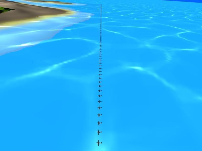
While I was playing around to develop a suitable water mode for the game, it became necessary to test water transparency. I still have not added ocean bed detail ..... only because I suck so much in creating graphics. The ocean bed is just a single color texture and that is all. ....... any good artists out there???

Anyway here is a shot from the "Bermuda Triangle" where a flight of P51D aircraft ran out of fuel and sank to the bottom in a sideways formation.
They are sitting 90M under the ocean.

Image
Syddy........Just another breed of COOL CAT
sydbod
Flight Sergeant
Flight Sergeant
Posts: 1678
Joined: Sat Aug 13, 2005 12:39 pm
Location: Sydney,NSW,Australia

Post by sydbod »

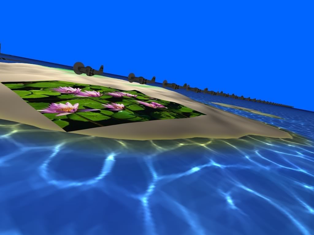
Was having a little fun integrating terrain into the model

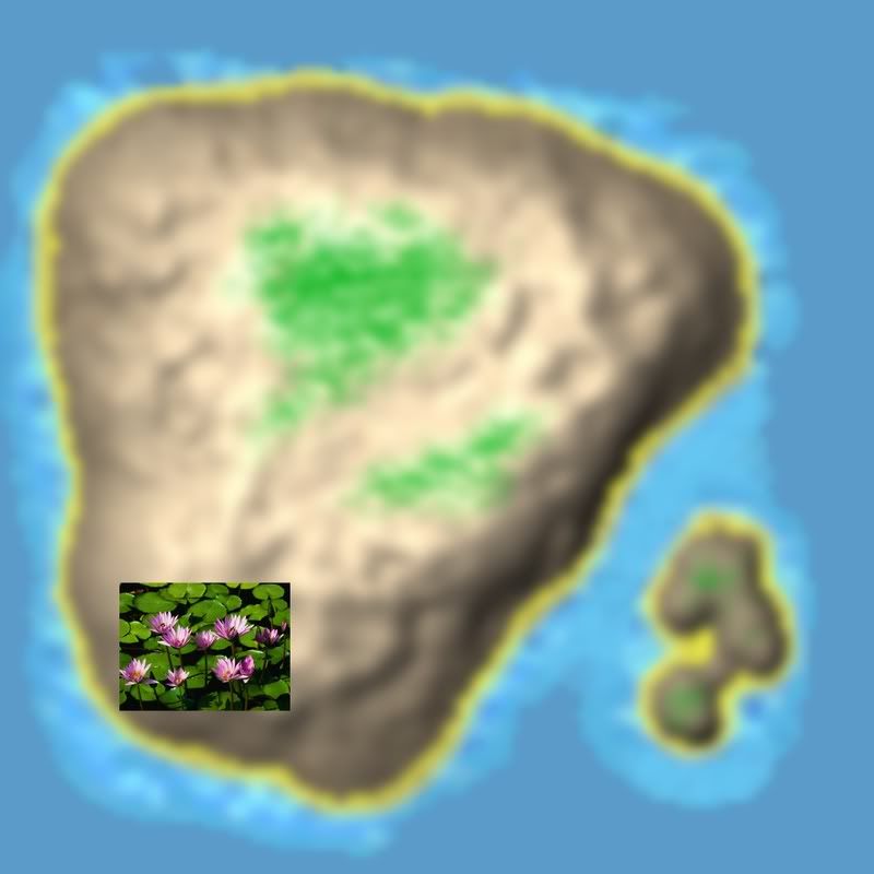
I included a few sandy atols but decided to determine what a good texture would look like.
Zoomed up the small crappy 128x128 texture for the island to 4096x4096 and then replaced a section of it with an 800x600 picture to determine what sort of detail is possible at such texture sizes.

Image

It looks like there is potential.
Syddy........Just another breed of COOL CAT
Shreck
Fitter Grade I
Fitter Grade I
Posts: 624
Joined: Sat Jul 31, 2004 4:39 am

Post by Shreck »

It looks like there is potential.

:shock: I'll say!!!!
I have been creating my EAW tiles as 512X512,then shrinking them to 256X256 :roll:
to have 1024X1024 tiles would be jaw-dropping :!:
BTW,what do you require in an ocean floor tile(s)?
Image
"Ask not what you can do for your country,ask,what has your country been doing to you!"
sydbod
Flight Sergeant
Flight Sergeant
Posts: 1678
Joined: Sat Aug 13, 2005 12:39 pm
Location: Sydney,NSW,Australia

Post by sydbod »

Hi Shreck,

Just some background info for you.

I am still trying to finalize a procedure for creating terrains for this new project. There are so many options and at the moment only one poor brain to try to think of all the options and how to implament them.

Things become even more complex because there is another updated version of the game library to be released in the near future and this will allow even more options to be used.

The basic format that I have been thinking about is the following:

1) An ocean floor made up of a mesh of 128X128 squares.
This ocean floor is scaled up to cover an area of 1,000,000 game units in width and in depth. A game unit represents 1 meter.
Therefor each square is a little under 8KMx8KM square.
This ocean floor is 90 meters under the ocean level.
Each of these ocean floor squares is currently textured by this one uniform color texture
Image
This texture ia currently only 256x256 pixels in size.
There is no reason why I can not use any even size from 2x2 pixels all the way up to 4096x4096 pixels.
This ocean floor is actually visible through the water surface.
The ocean floor texture only requires rough shade areas of different blue to create a realistic looking ocean depth.

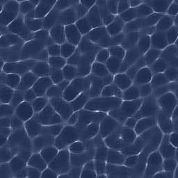
2)The ocean itself.
It is basically identical to the the ocean floor procedure, but sitting at a height of 0. this is my ocean level.
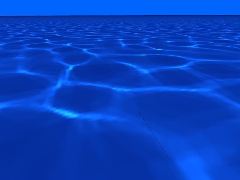
The texture that is being used is the following.
Image
The same as before applies to its size.
In the game, this texture is set to be semi transparent.
If I wanted higher water detail I could also make this texture all the way up to 4096x4096 in size, or I could increase the number of tiles making up the ocean from its current 128x128 squares, all the way up to 4096x4094 squares if I wanted.
I can also create a number of offsetted versions of the water texture and swap them out one after the other every 0.1 seconds and create what looks like moving wave patterns in real time without having to use any fancy or process heave video techniques.

The island is a similar technique but only scaled to a much smaller scale.
This land mas is made up of a grey scale picture where each pixel represents a node on a mesh.
This picture makes up the land mass.
Image
As it is 128x128 pixels in size, it will produce a mesh of 127x127 squares.
It is only scaled up by a factor of 5x . so each square is 5meters x 5 meters in size.
Again I can make it any size I like.
That whole landmass is sunk to sit on the ocean bed.
I could make many different landmasses of different sizes and make for instance an island chain or whatever.
For simplicity I texture the whole island mesh with a single texture of 4096x4096 pixels.
The reason I do this is, I can take the grey scale picture of the land mass and scale it up in a paint program to the size of 4096x4096.
Then I can paint over the grey shades with the land colors and water colors that I like.... I just paint the whole island in the one go, very quickly.
The part of the land mass that is underwater is painted with the same color as the ocean floor so it blends in properly.This is the land mass texture that I have used but at the 4096x4096 size.
Image


As you can see things are currently at a very simple level, but if people are interested in coming aboard and playing with it then a dialog has to be gone through as to what sort of actual terrain features are wanted.

IE: what size water and ocean dimensions are wanted.
How many land mass meshes as a max will be allowed in a game world.
How will we tell the game to put what island land mass to what game world co-ordinates....... there is a lot for ground work that is required, and it needs to be done by people with some vision of what they want the end result to be. For me it is only the challenge to understand how to create a game properly.

Should you be interested in some of the graphics areas with a vision of what YOU want to create, then you are more than welcome to come aboard and get involved in anything to do with this work.
It is NOT my project or any body elses project.
It is a learning experience for ANYBODY that has the interest to do something constructive with the material that will be created here.

The only thing I ask is that people are prepared to openly share what they create here, and that no old rivalries are carried across from the EAW forums ...... after all this is NOT EAW.
Syddy........Just another breed of COOL CAT
sydbod
Flight Sergeant
Flight Sergeant
Posts: 1678
Joined: Sat Aug 13, 2005 12:39 pm
Location: Sydney,NSW,Australia

Post by sydbod »

Greetings fellow travelers,

Some interesting developments have been under foot.
It is a good thing the Z Buffer approach was never implemented within EAW to replace the BSP system. Here is the continuation of the Rodnoc story so you hopefully will see the relevance to the above statement.

After playing around with new ways to create terrains, it became very obvious (very painfully noticeable actually) that my views were suffering from a thing called "Z Fighting".
This is where things like water lines can be seen through land masses because there is not enough precision in the Z Buffer to distinguish what is in front of what, when a large dynamic near/far camera view range is selected.
Let me explain.

Say one requires the camera (the thing that produces the image to the screen) to be able to see objects as close as 0.3meters from the camera (instrument panel), all the way 300Kmeter distance.
This is a near / far ratio of 1 to 1,000,000.
Now the Z buffer is a storage area where the distance from the view origin for a pixel is stored in. It stores values in a sort of logarithmic mode so that there is very high precision for things very close to the origin, but very low precision for things that are far away.
If there is a water plane lets say 1meter below a land plane, and one looks at this from around 50Kmeters away, then the "Z number" for the pixels for the water and the "Z number" for the land will be the same value. As one moves about, in one instant, the water will be drawn above the land, and the next instant , the land may be drawn above the water.

There are 2 ways to solve this problem.
1) get a video card that allows higher precision values in the Z buffer (a late model video card) and make sure the code actually sets the video card to use this higher precision, or else make the distance ratio from the near to far for the camera to be a much smaller value.
2)This second approach is what I have been playing with this last week.

I have actually made 2 cameras.
Camera 1 sees from 0.3meters up to 300 meters.
Camera 2 sees from 300meters to 300,000 meters.
This way each camera only has to view over a range of 1 to 1,000 and that can easily be accomplished with low end video cards and low end settings.
I just merge the 2 images together and produce a compound image.

I will next, introduce a 3rd camera to produce the 3D view cockpit image with the cockpit located at world co-ordinates of 0,0,0 so that the cockpit will not be jumping around when the aircraft is far away the the world origin (the early post about the jittering sphere), and hopefully the biggest problems will be solved.

There will still be a sh1t load of work in creating a "Frustum" culling system for 3 cameras, to increase the game FPS, and that will come after the 3 camera system is ready.

With some luck, I should have another version of this game ready to be flown by people in around 1 week time.

EDIT: before any one mentions a thing called linearizing the Z buffer to stop Z fighting at long distances ........ yes I did try that technique...... the close range views (cockpit) would then suffer badly from Z fighting) ... that is why the big work around with using 2 cameras.

Till next time :)
Syddy........Just another breed of COOL CAT
sydbod
Flight Sergeant
Flight Sergeant
Posts: 1678
Joined: Sat Aug 13, 2005 12:39 pm
Location: Sydney,NSW,Australia

Post by sydbod »

Just a quick update.

While doing some FPS testing on various machines, I came upon a situation where with the inclusion of just one more "Matrix" into the game, it would cause the game to drop from around 100+ FPS down to only 12FPS. EEEEK!!!!

This happened on a 754Pin Sempron 2800+ machine.
It has only 256K of Level 2 cache memory on the CPU and that extra "Matrix" looks to have pushed some vital time critical code out of the cache memory and thus is causing the massive drop in the frame rate.

To combat this I tried removing a few aircraft Objects from the game, but it made absolutely ZERO difference to the speed that the game played at.
After some more testing it became obvious that "Matrix" Objects have no way of being culled when not in view (in this game library), and no matter what one does, they just hog resources.

This is now forcing me to switch my terrain from "Matrix" based into "Mesh Object" based.
Standard Mesh Objects have very little overheads and can be easily worked with ........BUT....
This library does not have all the premade functions that I require to do what I want with Meshes.
Because I suck so much with anything to do with model making I was determined to make it easy for myself.
All parts of my terrain (ocean floor, ocean water, various islands, sun,....) will all be made from Meshes that get created from Grey Scale profile pictures.
This is forcing my to look at Mesh data structures and how to manipulate them.
My first attempt at this proved to be a disaster, because I tried to take a few shortcuts in what I was doing. This lead to a misunderstanding of a crucial part of the Mesh structure and the whole days worth of codeing will have to be scrapped.
Once again I have had to learn that there are no shortcuts in life and if anything is going to be done, then DO IT PROPERLY FIRST TIME.

Oh well maybe next weekend I may be ready to release another version as I will not manage it this weekend.

Back to the grindstone :sleep:
Syddy........Just another breed of COOL CAT
sydbod
Flight Sergeant
Flight Sergeant
Posts: 1678
Joined: Sat Aug 13, 2005 12:39 pm
Location: Sydney,NSW,Australia

Post by sydbod »

UMMM!!!!!! Ehhhh!!!!! gulp.

It looks like the transparent water was causing all the problems when a machine is using an early generation video card.

Oh well ..... I learned a lot in the exercise.

I know my graphics creations suck (so dont judge it on my graphics skills), but I liked the sun effect that Knegel got working within EAW, so I introduced the same sort of thing in this project.
Image
Image
Image
Image

I also had a very nice moving wave pattern on the ocean that is based on a moving texture. Will have to refine it a bit more as there ar 3 ways I can think to create the effect, and will have to see what way creates the least overheads.

Time for bed :sleep:

EDIT: Oh yes ... I finally got the transparency on models working.
The Z buffer is not a fix all solution as people may think.
It looks like the transparent parts on a model have to be the last polygons to be rendered otherwise the rest of the model that one sees through the transparency will not be rendered. So model creators have to be very careful of this point.
Syddy........Just another breed of COOL CAT
sydbod
Flight Sergeant
Flight Sergeant
Posts: 1678
Joined: Sat Aug 13, 2005 12:39 pm
Location: Sydney,NSW,Australia

Post by sydbod »

Hi All,

Just a quick update of what is being done.

I have decided to settle for something like a HD2400 (dirt cheap bottom end card) as the minimum video card for this project.
Likewise catering for 128 online players at the one time looks like it will be more than enough.

After spending the last 2 days optimizing some of the code, it is looking like these target will be attainable.

I still have not gone through the process of introducing a Level Of Detail system for the aircraft or the terrain, so there will be very significant gains to be made in these areas in the future when they get introduced.

The following screen shot was taken with all the aircraft at a higher polygon resolution than used in high rez eaw models. Needless to say most of the viewed aircraft should be no more than stick figures of a few polygons when LOD is introduced later.

When I first tried it, I was lucky to get over 20FPS and now it just reaches 60 FPS.

Image

How many aircraft can you count ........ If you say 200 aircraft then you are close, but not quiet on the exact number.

I also wanted to make sure the networking code could handle well over the 128 chosen aircraft limit.

Regards sydbod :)
Syddy........Just another breed of COOL CAT
RAF_Dumoulin
Fitter Grade I
Fitter Grade I
Posts: 638
Joined: Mon May 10, 2004 9:36 am
Location: Kingdom of Belgium
Contact:

Post by RAF_Dumoulin »

Hello Syd,

Thank's for headup.
I follow this saga .. when time or my memory allow :)

Regards.

Gus.
A common mistake that people make when trying to make something completely foolproof is to underestimate the ingenuity of complete fools...

http://eaw.wikispaces.com
http://gusthesailor.proboards.com/index.cgi?
RAF_Dumoulin
Fitter Grade I
Fitter Grade I
Posts: 638
Joined: Mon May 10, 2004 9:36 am
Location: Kingdom of Belgium
Contact:

Post by RAF_Dumoulin »

Hello Syd,

Just a link I found ... maybe some interests for you ?
It's just to read after all :)
http://lotus-films.blogspot.com/2008_08_01_archive.html

Regards.

Gus.
A common mistake that people make when trying to make something completely foolproof is to underestimate the ingenuity of complete fools...

http://eaw.wikispaces.com
http://gusthesailor.proboards.com/index.cgi?
Wudpecker

Post by Wudpecker »

Intriguing research and testing, Syd.

Dealing with water fascinates and frustrates. Motion and color are two parts to simulate. Patterning and refraction are two others.

The patterning you chose is a very good one.
Image
It should be possible to shift the pattern either with a sine-wave rise, fall, and re-size formula. Or more simply with an artist's sprite that does the same thing. Let the artist get a headache! :shock:
Then slow changes in the pattern will suggest large, languid water areas.
Fast changes we will associate with smaller, restless water areas. OR with submerged objects like your aircraft. Read on.

The water areas you have chosen are a bit too large for a realistic pattern appearance of this type, in my view. Each "cell" is probably best around 3 feet or less.
Collapse and shifting of each cell makes the water 'move'.

The advantage of this particular moving pattern is that it makes it possible to simulate "seeing" into or below the water surface. By replicating the reduced-size pattern on the submerged object, a sense of depth is achieved.
The more shifting of the submerged object, the deeper it appears to be.
Whether you could apply the pattern so it stretched and wiggled the 'submerged' object is an interesting mental exercise.

When the sine wave ~ goes from large and slow to small and fast ~, it will begin to change into surface wave breaks along the shorelines and occasionally at sea.

Here's a positive use for your imprecise distance locations by floating-point numbers.
When doing seas, I and other terrain artists use a little near-white 'smudge' line to simulate the wave breaks. The shimmer of most video cards make it appear to move just enough to resemble the real thing. Floating-point imprecision may be the cause.

Another use for patterns or 'billboard' terrain pics might be to overlay the featureless ground smears (anti-aliasing ) on close-up view with some detail.
Don't know if this type of overlay is possible. But intriguing to think about.
sydbod
Flight Sergeant
Flight Sergeant
Posts: 1678
Joined: Sat Aug 13, 2005 12:39 pm
Location: Sydney,NSW,Australia

Post by sydbod »

Hi Dumo,

A most interesting article.
I have been spending many sleepless nights thinking about what that article talked about.

The ground shadows cast by aircraft in FSX are calculated straight off the polys themselves and the more of them you have the more performance you lose. In case you don't believe me just load up your favorite high end add on aircraft, turn off the aircraft ground shadows in your display settings and watch what happens to your frame rate. ;) This alone, or any two pass render effect (water, bloom) makes a strong case for efficient modeling, or at the very least for the return of low-polygon proxy shadow models.


I totally agree with this part "or at the very least for the return of low-polygon proxy shadow models."

I have been planing on making my distance model from 8 surfaces so that would be around 20 to 30 polygons. I was also planning to use it for creating my shadows when the aircraft gets close enough to the ground.

This exercise has been a great learning experience .

Hi Wuddy,

Yes there are many effects that one can use to simulate water.
Those tricks that are used in EAW are very efficient, but maybe with having access to the huge computing capability within modern video cards, there may be other options worth pursueing also. This is a learning exercise after all so what the hell, why not have some fun.

In modern 3D objects, it is the direction of rotation of the nodes making the polygons that determine what direction a surface is facing, but it is the direction of the normals that determines the angle of reflection of light off that part of the surface.
It is possible to jiggle the angle of the normals to positions other than perpendicular to a surface and thus cause light reflections to look at different strengths at different areas of a flat mesh.
One should be able to simulate the appearance of what the reflected light would look like from a slowly undulating ocean without too much processing overheads. Add in some tricks like you suggested a slight smudging of the white highlights areas of the texture, and add in some dynamic remapping of the texture to the water mesh, so that the water texture actually moves, and one could have a very realistic ocean.


Of current interest, I have been battling with a bit of mathematics over the last week or so.
It is dealing with Euler angles and Quaternions.
Basically in 3D space a model gets rotated around its OWN axis in a certain order to determine its orientation in free space.
Since computers calculate computations, one at a time (sequentially) one has all sorts of problems. Depending upon what order one does the rotations around the aircraft axis will produce different orientation outcomes for the aircraft.

If one were to take an aircraft that is pointing away from you and pitch it upwards from its horizontal direction, and roll it to its right right, and yaw it to its right, it will be in different positions depending upon the order one does it.
EG: If we do the order as pitch, roll, yaw, then the aircraft will be pointing in the same direction that it started, but have only changed as if it only did a roll to the right along its axis.
If we do the order of roll, pitch, yaw, then the aircraft will be pointing its nose downwards, and the cockpit will be pointing backwards from the original direction of the aircraft.
It all can become very confusing unless one takes very careful consideration of being consistant in the sequence order of how things get rotated.
Also things like Euler angles become very complex when trying to extract things like resultant aircraft compass direction, or resultant aircraft pitch. So one has to start doing all sorts of positional representation directions in other formats like Quaternions. A sh1t load of mathematics gets involved in this conversion process.
One also has to try to reverse engineer what the particular game engine does for its reference axis to be able to determine in what order that particular game engine is rotating its Euler angles so that the correct transformations from Euler to Quaternion can be accomplished.

I just don't know if I will live long enough to do all the research that is required to achieve a finished game. :(

Regards till next time. :)
Syddy........Just another breed of COOL CAT
Post Reply